Trajectories and UAVs: moving receivers, playback, and POV views
A static TX→RX solve tells you one snapshot; a trajectory tells you how the link evolves as a receiver flies, drives, or walks through the scene. This guide covers the two ways to move a UE, UAV actors with attached antennas, the exact semantics of trajectory playback in the viewer, and the per-entity POV inset. Everything here works with the Mock backend alone — no GPU or Sionna RT installation required.
1. Two ways to move a UE
| Approach | Where | What moves |
|---|---|---|
| Device trajectory | Results mode → UE trajectory panel | An existing RX device is swept along a start→end line or drawn waypoints; one solve per step. |
| Actor flight path | Select an actor → inspector TRAJECTORY section | The actor (e.g. a UAV) follows its own authored waypoints; an attached RX rides along and flies the path. |
Both feed the same trajectory engine: the result is a time-series of samples (RSS / path gain / SINR / RMS delay spread / path count per step) plus per-step live rays you can play back in the viewer.
2. Device trajectory — the UE trajectory panel
- Switch to Results mode and find the UE trajectory panel (dockable, like every panel — move it with ◧/◨/⧉).
- Define the route. Three options:
⌖ Pick start → end in viewport— click two points in the 3D view: first the start, then the end (Esc cancels). A dashed yellow preview line shows the segment. Start at RX seeds the Start / End fields from the current first RX position instead.- Draw route (Esc finishes) — click waypoints one by one in the 3D view; Esc finishes the route (at least 2 points). With more than one RX in the scene, a selector chooses which RX the drawn route belongs to, so you can author one route per UE and they all move together.
⤓ Import JSON— load waypoints from a JSON file. Cartesianx/y/zor geographiclat/lonpoints are auto-detected (geographic needs the scene's geodetic anchor), and underground points are flagged with a ⚠ warning on the route row. Files with per-waypoint antenna orientations show an oriented chip. Format details: ../point_import.md.
- (Optional, outdoor) Check Follow terrain to drape each waypoint onto the surface below it plus the UE height offset — keeps the UE at a constant height above sloped ground. Leave it off indoors.
- Set Num points (2–200 solve steps; every route is resampled to this step count) and dt (seconds per step).
- Press Simulate trajectory. Each step is a full TX→RX solve at the moved position; with multiple TX the per-step SINR and interference appear too. With routes for several UEs, Include fixed UEs also solves every un-routed RX at its fixed position each step.
The result strip shows the UE id, a moving UE chip, the sample count and backend, and a ✕ Remove button that clears the marker/trail/ray overlay immediately.
3. UAV actors
Create and pose
In the scene tree's ACTORS row, press +UAV (next to +Car, +Human, +Custom). The UAV spawns hovering above the scene center. Select it and the inspector shows Actor · <id> with a POSE & SIZE section: Name, X / Y / Z (m), Yaw (°), Length / Width / Height (m), then Apply. Positions are Z-up ENU meters (X east · Y north · Z up); yaw rotates about +Z. You can also drag the actor with the viewport gizmo.
The UAV renders as a procedural quadrotor (fuselage, four rotor arms, skids, gimbal camera). In large outdoor scenes the visual model is scaled up to device-marker visibility — a real 0.6 m drone would be sub-pixel at campus scale — while the RF projection keeps the true size_m box.
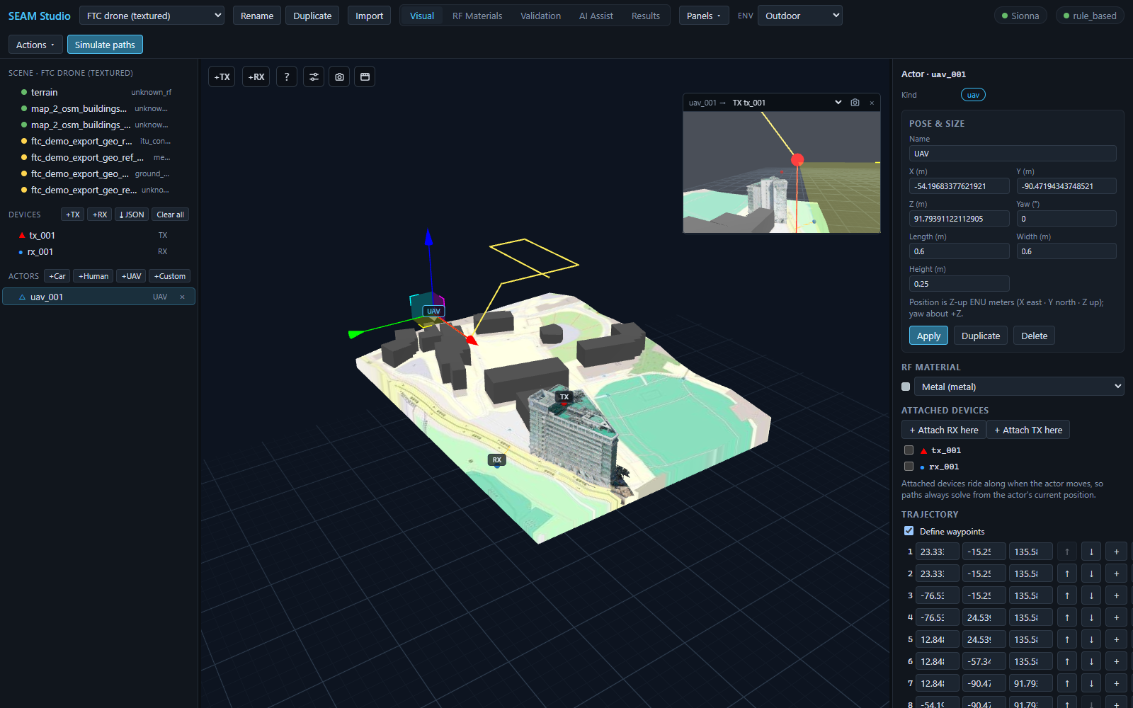
uav_001: gizmo + yellow flight path in the viewport, the live POV inset (uav_001 → TX tx_001), and the actor inspector with + Attach RX here / + Attach TX here and the waypoint table.Attached devices — how an actor becomes an RF endpoint
Actors are scatterers; rays terminate at antennas. To make a UAV an RF endpoint, open ATTACHED DEVICES and press + Attach RX here (or + Attach TX here for a UAV relay/base station). This creates the antenna on top of the actor and checks it in the attached-device list. Attached devices ride along when the actor moves, so paths always solve from the actor's current position.
Flight path — the TRAJECTORY section
Check Define waypoints in the TRAJECTORY section to give the actor a flight path. Each waypoint row has:
- the row number (click to highlight that waypoint in the 3D view),
- editable X / Y / Z fields,
- ↑ / ↓ to reorder (swap with the previous/next waypoint),
- + to insert a waypoint after this one (midpoint to the next; +2 m in X after the last),
- × to remove it (blocked at 2 waypoints — a trajectory needs at least a segment; uncheck Define waypoints to remove the whole path).
Below the table: + Waypoint appends the actor's position, ⌖ Pick waypoint appends a clicked point from the viewport, and Record current pos captures the pose you just dragged to. dt (s) and Mode (once / loop / pingpong) control the animation, which plays in Results → Scenario playback (Simulate scenario animates every actor along its own waypoints).
⚡ Simulate paths along trajectory
The ⚡ Simulate paths along trajectory button (enabled with ≥ 2 waypoints and an attached RX) sends the actor's waypoints straight to the trajectory engine: one TX→RX solve at each step along the flight path, with per-step rays. The attached RX is what flies the path — without one the button's tooltip tells you to attach an RX first. Results land in the UE trajectory panel exactly like a device trajectory.
4. Trajectory playback — exact semantics
A trajectory result adds a playback transport under the UE trajectory panel: ▶ / ⏸, a frame slider with a frame/total counter, ⟳ repeat, and a speed select (0.5×–4×). Multi-UE runs add per-UE scrub bars and a KPI UE selector. The viewer behavior is deliberately strict:
- Running a trajectory engages playback. A fresh Simulate trajectory (or ⚡ from an actor) turns the Trajectory rays overlay toggle on and shows a moving UE marker (scene-scaled, slightly smaller than static device markers) plus that step's rays. Scrubbing the slider or pressing ▶ moves the marker and re-draws the per-frame rays.
- Static device markers always stay at their scene positions. The moving marker is an overlay; the RX device itself never teleports, and its static marker is never hidden.
- Pressing
Simulate pathsfully disengages playback. The viewer switches to the fresh static paths result: the Trajectory rays toggle turns off, playback stops, and the frame (and any per-UE scrubs) reset to 0 — the moving marker disappears rather than lingering as a phantom "moved RX" next to the new rays. Both overlays remain independently toggleable afterwards. - Reopening a project arrives disengaged. A stored trajectory result auto-loads so the transport and charts are ready, but the Trajectory rays toggle starts off — no marker appears until you press ▶, scrub, or re-enable the toggle.
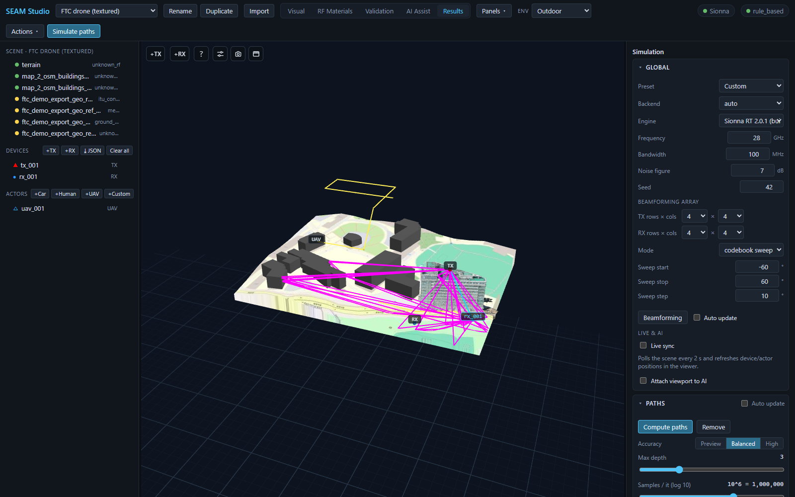
rx_001 marker; the static TX/RX markers stay exactly at their scene positions.5. The entity POV inset
Click any TX, RX, or actor and a live inset opens in the top-right of the viewport: it renders that entity's point of view toward its link partner. The header reads e.g. TX tx_001 → with a partner selector (a TX looks at the first RX by default; everything else looks at the first TX). During trajectory or scenario playback the inset tracks the live rendered pose. The source's own airframe is hidden in the POV pass, so a UAV's camera is not blocked by its own rotors. The camera button saves the POV view as a full-resolution PNG; × closes the inset (it reopens on the next selection).
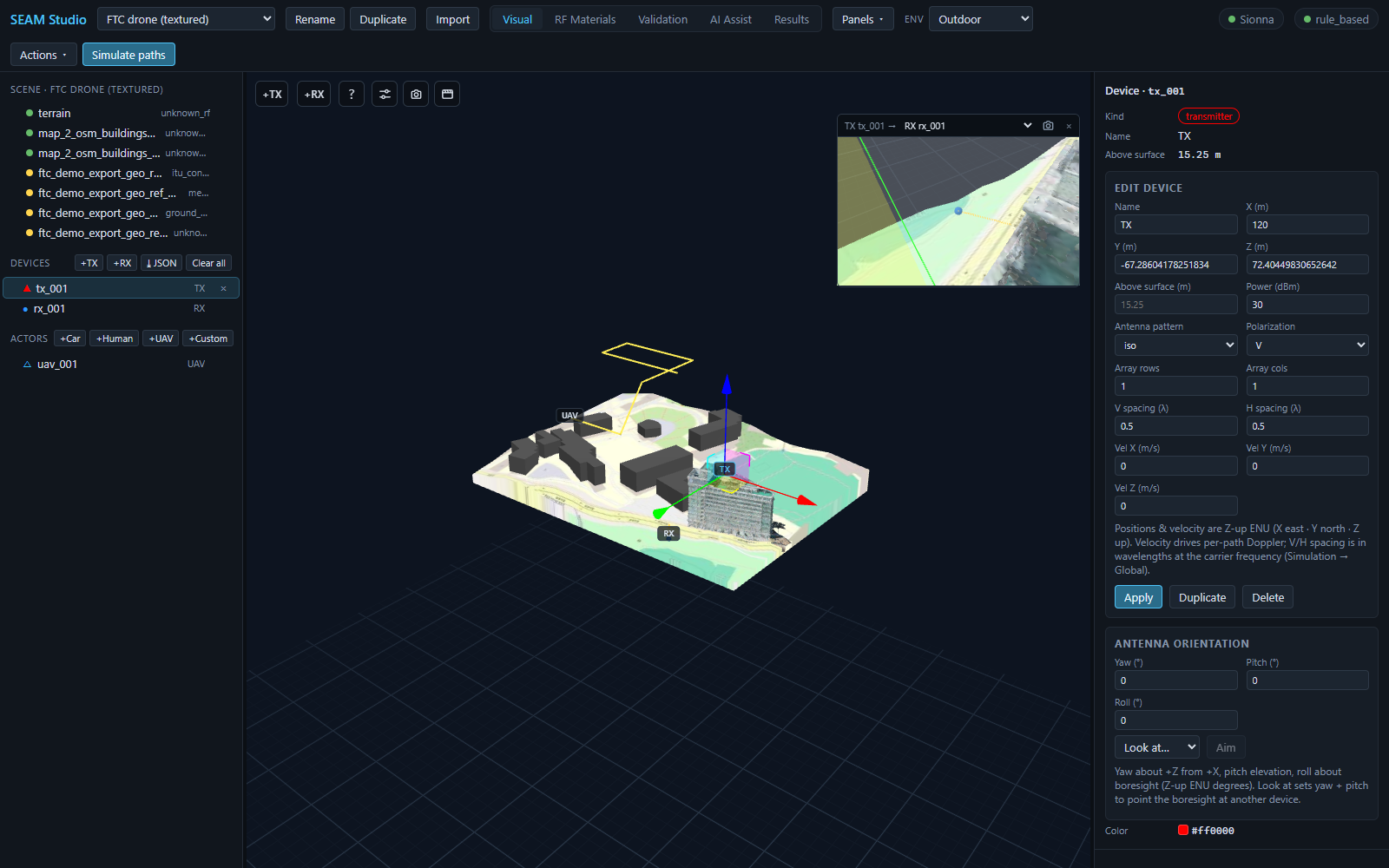
tx_001 selected, the inset shows TX tx_001 → RX rx_001 along the green LOS ray. The inspector's ANTENNA ORIENTATION section (Yaw / Pitch / Roll, Look at…, Aim) points the boresight at another device.Related: the device inspector's ANTENNA ORIENTATION section sets Yaw (°) / Pitch (°) / Roll (°) directly, or pick a target under Look at… and press Aim to point the boresight at it — handy for aiming a directional TX at the UAV you just flew.
6. Where the numbers go
The playback strip shows per-frame KPIs (t, position, RSS, Path gain, SINR/SNR, RMS delay, Paths). For the full time-series, open the Metrics dashboard panel: once a trajectory result exists it adds paper-style charts — Trajectory: power vs time (RSS/SINR, derived RSRP), RMS delay spread vs time, path count vs time, plus Doppler and serving-cell/handover views when available — each with PNG/SVG/CSV export. Trajectory samples also feed ML datasets (trajectory sampling mode, see ../ml_datasets.md) and the RFData export (trajectory.csv).
Related docs
- simulation.md — the static solves this guide builds on (paths, radio maps, channel analysis)
- ../point_import.md — JSON waypoint/device import formats (cartesian & geographic)
- ../../TUTORIAL.md — 15-minute first session, including a quick trajectory run
- datasets_export.md — ML datasets (trajectory sampling mode) and RFData export
- ../dynamic_scattering.md — how moving actors are compiled into RF geometry
- materials_and_ai.md — assigning RF materials (actors have an RF material too)